3. Airplane propulsion
The objective of this document is to provide a simple description of the way an aircraft engine which is commonly called a jet engine is working. Many systems of propulsion have been developed in aeronautics. We will concentrate here on the gas turbine, which is most commonly used in civil aviation. This document also covers the technologies now in use to limit the emission of polluting gases. The use of specialist vocabulary and mathematical formulae is avoided as far as possible to concentrate on a clear and concise description of the fundamental principles.
3.1 The aircraft engine – basic definitions
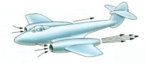
Principle of aeronautical propulsion
© Copyright Rolls-Royce plc 1996. All rights reserved. This copyright work has been reproduced with the kind permission of Rolls Royce plc.
Before discussing the main subject, it is necessary to establish some basic definitions. The Merriam-Webster dictionary defines an engine as a machine for converting any of various forms of energy into mechanical force and motion. The engine is thus an energy transformer. Energy (also called work, and quantified in Joules) can itself be interpreted as a force in motion. In the well-known case of a car engine, the thermal energy coming from the 20 combustion of petrol and air is transformed into mechanical energy which is applied to the wheels of the vehicle (the force allowing to turn the wheels).The more familiar notion of power, quantified in Watts (or in horse-power by our parents and grandparents – 1 horse power = 736 Watts) expresses the quantity of energy used in one unit of time.
This transformation is unfortunately not perfect and is necessarily accompanied by certain losses. This introduces the notion of efficiency. The efficiency is defined as the ratio between the result obtained (the mechanical energy transmitted to the wheels in the example of a car engine) and the means used to produce it (thermal energy contained in the petrol-air mixture in this example). Its value is always less than 1 (or 100%). As an example, a petrol engine and a diesel engine give respectively efficiencies of the order of 35% and 46%. In a traffic jam, this efficiency can reduce to 15%. The lost energy is generally transformed into heat.
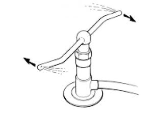
Watering system driven by the reaction of water jets.
© Copyright Rolls-Royce plc 1996. All rights reserved. This copyright work has been reproduced with the kind permission of Rolls Royce plc.
In flight, an aircraft does not have wheels in contact with the ground. We therefore need to define the way of generating energy to allow it to advance. The principle of aeronautical propulsion is a direct application of Newton’s third law of motion (principle of opposite action or action-reaction) which says that any body A exerting a force on a body B experiences a force of equal intensity, exerted on it by body B. In the case of aeronautical propulsion, the body A is atmospheric air which is accelerated through the engine. The force – the action – necessary to accelerate this air has an equal effect, but in the opposite direction – the reaction -, applied to the object producing this acceleration (the body B, that is the engine, and hence the aircraft to which it is attached).
The functional objective of the aircraft engine is thus to produce a large quantity of air (a large flow rate) exiting the engine at high speed (a speed much higher than the speed of the aircraft).
The first picture illustrates this principle.
It is possible to imagine much simpler examples based on the same principle. The first, probably the most simple, is that of the fairground balloon, which is first inflated then released. The air (body A) is ejected from the balloon (body B) through a small opening and at high speed. The balloon is propelled in the opposite direction to the ejected air – this is the reaction (see the experience proposed at paragraph 2.2). The second example is that of a rotating watering system (In the second picture).
The speed of water (body A) is increased by its passage through small ejection holes. The two arms of the watering system (body B) are pushed in the opposite direction (reaction), thus driving the rotation.
3.2 The gas turbine: architecture and functional principle
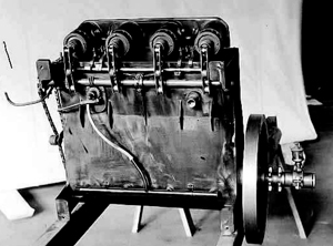
First motorised flight by the Wright brothers (1903) Wright brothers engine
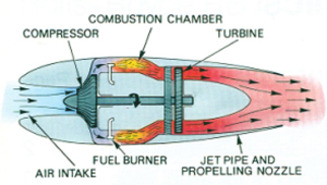
Sir Frank Whittle s gas turbine engine
© Copyright Rolls-Royce plc 2005. All rights reserved. This copyright work has been reproduced with the kind permission of Rolls Royce plc.
The first motorised flight of an aircraft dates from 17th December 1903 (On the left picture) and was carried out by the brothers Wilbur and Orville Wright on the beach of Kitty Hawk in North Carolina (USA). The flight lasted 12 seconds and a distance of 36 metres was covered.
The application of the gas turbine to aeronautical propulsion dates from the 1930s. This engine (the gas turbine) was developed independently in Great Britain by Sir Frank Whittle (first patent in 1930, first flight on 7th April 1941) and in Germany by Hans Joachim Pabst von Ohain (first patent in 1936, first flight on 27th August 1939). We can see that the progress in aeronautics occurred at an incredible speed.
The gas turbine used as an aircraft engine by Sir Frank Whittle is presented on picture above on the right. The second on the right shows a photo of the aircraft in flight with this engine installed.
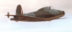
The Globstar E28/39 aircraft equipped with Sir Frank Whittle s engine (1941).© Copyright Rolls-Royce plc 2005. All rights reserved. This copyright work has been reproduced with the kind permission of Rolls Royce plc.
The example proposed here is the simplest architecture that can be imagined for an engine. This architecture is composed of 5 main parts:
- the air intake
- the compressor
- the combustion chamber
- the turbine
- the outlet (jet pipe and propelling nozzle)
The purpose of the following paragraphs is to
- suck atmospheric air into the engine (air describe briefly these components. Their inte- intake and compressor) gration serves to:
- increase the energy of this air by means of the compressor (increasing the pressure) and the combustion chamber (increasing the temperature by burning a mixture of air and kerosene)
- transforming this energy into speed (kinetic energy) by means of the outlet tube in order to apply the principle of aeronautical propulsiondescribed above.
The air intake
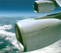
Air Intake
The air intake is one of the most visible parts of an aircraft engine. A typical photo of this component is shown on the right picture. This envelope which precedes the main part of the engine is attached to a strut, which is itself fixed to a wing or the fuselage. The main purposes of this nacelle are:
- to present as little air resistance (drag) as possible
- to guarantee optimal functioning of the engine during the different phases of flight (take-off, cruise, landing)
- to limit the acoustical disturbance of the engine by absorbing some of the noise
- to protect the inlet parts of the engine from phenomena relating to icing (the local temperature at 10 000 metres altitude is between -40° and -50°C)
The compressor
The compressor, situated just behind the air intake, is the first element which allows transformation of energy, in this case from mechanical energy into energy in the form of pressure. This machine is presented at the bottom left, where the flow is from left to right.
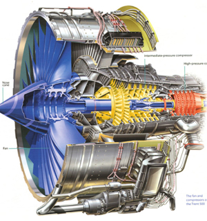
The compressor from the engine of a modern civil transport aircraft
© Copyright Rolls-Royce plc 2005. All rights reserved. This copyright work has been reproduced with the kind permission of Rolls Royce plc.
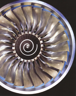
Fan of the engine of a modern civil transport aircraft (seen from front)
© Copyright Rolls-Royce plc 2005. All rights reserved. This copyright work has been reproduced with the kind permission of Rolls Royce plc.
The compressor is composed of a series of fixed blades, both fixed (stators – coloured in grey in the figure) and moving (rotors – coloured in blue, yellow and red in the figure). The function of these blades is to transform the mechanical energy which turns the rotors into pressure energy. This transformation operates by directing in a precise way the flow which develops in the channels defined by the blades and the envelope of the engine. The rotor which is best known is the one coloured in blue in Figure at the left; this is also called the fan and can be seen at the entrance of the engine (Figure at the right).
Air from the atmosphere is sucked into the engine by the compressor in the same way that a ventilator fan (which is nothing else but a type of compressor) sucks air into a polluted room.
The compressor of a modern engine allows pressures typically 30 or 40 times greater to be reached at the outlet of this element. The fan turns at a rotational speed of the order of 5000 revolutions per minute: the largest diameters are of the order of 3.25 metres, the length of the blades of the largest fans is greater than 1.20 metres. The centrifugal force undergone by transport aircraft these rotating blades is comparable to the weight of a railway carriage (80 000kg) being attached to the end of one of these blades.
The combustion chamber
The combustion chamber, situated just downstream from the compressor, is the element in which thermal energy is added to the pressure energy accumulated at the outlet of the compressor. The transformation of energy considered here comes from the combustion of the air/kerosene mixture (the combustible used in most aircraft engines) which generates an increase in the temperature of the air passing through the engine.
Calculations show that the efficiency of the engine will be better if the temperature at the outlet of the combustion chamber is higher. In the most recent engines, temperatures of the order of 2100°C are achieved. To understand this temperature, it is useful to remember that the temperature of the flame of a wood fire is only about 1000°C. The materials used for the construction of a combustion chamber contain an important fraction of nickel and chrome. The melting temperature of these two metals is less than this 2100°C and protection and cooling of the metal parts is therefore absolutely necessary. A description of such technologies is outside the scope of this document.
In summary then, at the outlet of the combustion chamber, there is a mixture of burnt air and kerosene at very high temperature and pressure.
This energy (in the form of pressure and temperature) results from the transformation of mechanical energy necessary to turn the compressor and the transformation of chemical energy contained within the kerosene, which is stored in the fuel tanks of the aircraft. We now need to define the source of mechanical energy required to turn the compressor. This is the role of the turbine.
The turbine
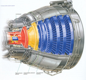
Turbine of the engine of a modern civil transport aircraft
© Copyright Rolls-Royce plc 2005. All rights reserved. This copyright work has been reproduced with the kind permission of Rolls Royce plc.
The turbine is situated at the outlet of the combustion chamber. Its function is to transform the energy available in the form of pressure and temperature into mechanical energy. In other words, the turbine is the “motor” which turns the com- pressor. The pressure and temperature of the airkerosene mixture will decrease during passage through this element. This part of the machine is presented in Left Figure.
As for the compressor, the turbine is composed of a series of blades, both fixed (stators – coloured in grey in the figure) and moving (rotors – coloured in red, yellow and blue in the figure). The function of these rotors is to transform the temperature and pressure energy into mechanical energy which turns the compressor. This transformation is also made by precisely directing the flow which develops in the channels defined by the blades and the envelope of the engine. As an example, the red rotor in Left Figure is generally composed of 30 to 40 blades. Each one of these generates the same energy as is generated by the entire engine of a Formula One car!
Calculations show that the complete transfor- mation of the energy available in the form of pressure and temperature and the energy available in the kerosene gives more mechanical energy than is needed to turn the compressor (typically twice as much). The turbine serves then to transform only the quantity of energy strictly required to achieve this function. The 50% available energy which remains in the air/kerosene mixture is transformed into kinetic energy (the speed necessary to guarantee propulsion of the aircraft).
The outlet tube
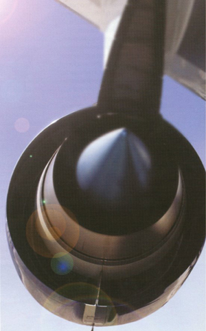
Outlet tube in the tube, mixing this with the flow
© Copyright Rolls-Royce plc 2005. All rights reserved. This copyright work has been reproduced with the kind permission of Rolls Royce plc.
This last element, situated at the back of the turbine, is the outlet tube. In this tube the last transformation of energy takes place with the aim of creating a jet of air exiting the engine at high speed, thus allowing the propulsion of the aircraft according to the principle of action/reaction. This transformation is achieved by a controlled variation of the cross-section of the outlet tube. A typical example is shown in the centre of Figure 10, which is a photo of the back of a aircraft engine.
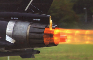
© Copyright Rolls-Royce plc 2005. All rights reserved. This copyright work has been reproduced with the kind permission of Rolls Royce plc.
In the case of Concorde (a now discontinued supersonic civil transport aircraft) and in the case of a number of military aircrafts, a final transformation of energy, afterburning, is made in the outlet tube. The principle of this transformation is to inject extra kerosene and burning the mixture. The extra energy obtained gives an even higher speed to the jet of air exiting the engine and hence an even great propulsive power. A photo of the outlet jet, with afterburn, is shown in Figure 11. This technology is mainly used for aircraft flying at speeds greater than the speed of sound.
3.3 The gas turbine: effect on the environment (CO2 emission)
Carbon dioxide (CO2) is a chemical compound with a molecule composed of one carbon atom and two oxygen atoms. It is generated by the combustion of the air/kerosene mixture. Kerosene is an extract of petrol – it is a fossil fuel and therefore contains carbon. Above a certain concentration in air, this gas becomes dangerous, or even mortal. The threshold con- centration for exposure is 3% for a duration of 15 minutes.
The second harmful property of CO2 is that it is a greenhouse gas. When solar radiation reach- es the earth’s atmosphere, a part (about 30%) is directly reflected, sent back into space, by air, by white clouds and by the bright surface of the earth, particularly in white and glacial regions such as the Arctic and Antarctica. The incident rays that are not reflected back into space are absorbed by the atmosphere (about 20%) and/or by the earth’s surface (about 50%). This part of the radiation absorbed by the surface of the earth brings heat, i.e. energy, to the ground. This heat energy is in turn reemitted, day and night, in the direction of the atmosphere as infrared radiation. This infrared radiation is then partially absorbed by greenhouse gases, which heat the atmosphere. Finally this heat in the atmosphere is reemitted in all directions and notably towards the earth. It is this radiation of heat back towards the earth that forms the greenhouse effect and is an extra source of heat for the earth’s surface. The increase in the concentration of CO2 in the earth’s atmosphere, therefore, contributes to climate warming. The process is summarised in the following picture.
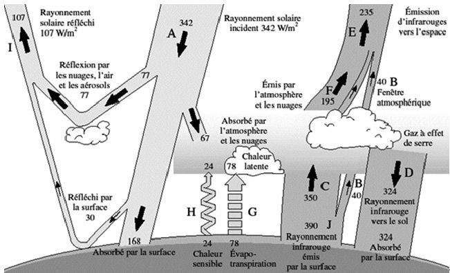
Exchange of energy between the earth and space the greenhouse effect
In order to understand the importance of the effect of CO2 with respect to aeronautical propulsion, it is useful to consider the follow- ing data:
- the proportion of CO2 in the atmosphere (2007): 0.04%
- the contribution of CO2 to the greenhouse effect: 55%
- the contribution of air transport to CO2 emis- sions: 2.5%
Another example can be used. Consider a jour- ney from Charleroi to Carcassonne:
- In a Boeing 737 with 160 passengers
- In a diesel car
- In a powerful motorbike
The amount of CO2 production is as follows:
- The aircraft produces 79.5 kg of CO2 per passenger (duration of journey: 1h35)
- The diesel car produces between 80 and 120kg of CO2 (duration of journey: 9h30)
The motorbike produces 120kg of CO2. One of the principal objectives of the industry which constructs aircraft engines is to reduce this production of CO2. Many directions are available to:
- reduce the consumption of fuel
- increase the efficiency of the components of engines
- find alternative fuels
Reduction of consumption
The next picture ("Reduction of fuel consumption over the last 40 years") shows the reduction in fuel consumption obtained over the last 40 years for standard civil aviation engines. It is clear that an economy of about 40% has been achieved over this period.
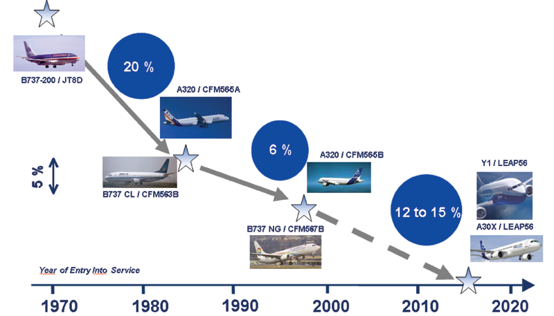
Reduction of fuel consumption over the last 40 years
Today, the most modern engines have a con- sumption of less than 3 litres of kerosene per 100km per passenger.
Improvement of efficiency
The turbojet is the type of engine which proba- bly has the highest power/weight ratio. Put differently, for a given power, it is the smallest (or lightest) engine. For example, one engine of a Boeing 777 (GE90), which is currently the world’s largest aircraft engine, is twice as powerful as the engines of the Titanic ship and 1000 times more powerful than a formula one car engine.
The research carried out today by industry, helped by research institutes and universities, aims to obtain a better efficiency from the dif- ferent components of a turbojet. These studies consider:
- The aerodynamic form of the different ele- ments: the air resistance should be as low as possible. This concerns mainly the shape of the winglets of the compressor and the turbine.
- The weight of the components: the different elements should be as light as possible. The weight of the GE90 engine mentioned above is about 7.5 tons. Significant efforts are being made to reduce this weight by developing or trying new materials. For example, the blades of the fan of the GE90 are made of composite material. If they had been made of titanium, as for the great majority of other engines, the GE90 would weigh 300kg more.
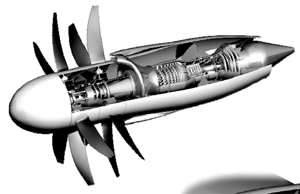
Schematic view of the Open Rotor
- The architecture of the engines: the construc- tors are thinking now about the architecture of the engines of tomorrow. The main projects con- sidered today concern the “open rotor”, the counter-rotating fan, and the fan with gearbox.
The first concept (in the picture "Schematic view of the Open Rotor") is radically different from what we see today. It has a low consumption, but high noise; the second concept concerns limiting the weight of the engine, but increases the technological difficulty, because it involves turning the rows of the fan in an opposite direction; the third concept allows to decouple the speeds of rotation of the turbine and of the compressor and thus to make this more compact, and hence lighter. An optimum should therefore be found between the advantages and disadvantages of these ideas.
Research on alternative fuels
Aircraft engines now have greater and greater efficiency. The aerodynamic, thermal and mechanical performance of the different components is getting better and better and the weight of the engines is ever decreasing. Research and development in all these domains is more and more advanced. However, the overwhelming majority of turbojets still use kerosene as fuel. Kerosene is a derivative of petrol and is composed of a large number of hydrocarbons (molecules containing chains of carbon).
The industrial companies which make aircraft engines have at last decided to invest in the search for and application of alternative fuels. A first reason to use such fuels is to reduce the production of CO2 as well as pollutants such as sulphur oxides (SOx) and nitrous oxides (NOx), and to thus improve air quality, especially in the regions around airports. A second reason is related to the price of petrol. In 1999 a barrel of petrol cost 10 dollars. Today it costs nearly 75 dollars. Moreover, petrol cannot be produced eternally. It is therefore necessary to find alternatives.
The basic principles for the use of alternative fuels, or bio-fuels, are the following:
- They are produced from renewable biological resources such as plants (which is strictly speak- ing true also for petrol except that petrol takes millions of years to make). The CO2 produced by combustion is thus dispersed in the atmos- phere.
- The CO2 in the atmosphere is absorbed by plants (biomass) when they grow. This same CO2 returns into the atmosphere when the biofuel is burned. The global impact is thus zero (See "Production, transport and use of bio fuels").
- The first generation bio-fuels have already been in use for a number of years in applications other than aeronautics such as transport, heating and the production of electrical energy. These first generation bio-fuels are extracted mainly from food products. A number of classes can be distinguished including “oils” (sunflower, rape, castor, etc.), “alcohol” (sugar cane, beetroot, maize, wheat, etc.), “gas” (methane produced by solid waste from water treatment plants, manure and household waste) and finally “charcoal”. A large proportion of these raw materials comes from food resources.
- Second generation bio-fuels come from new, purely energetic sources, not used by the food industry. They are made from wood (lignite and cellulose), transformed into gas or alcohol, from algae, from inedible plants, or from oil-producing oil trees, which are also used to combat desertification
- Third generation bio-fuels are extracted from algae (also called algal fuels). This sub- ject is still in a research phase. Some scientists claim that these micro-algae could be between 30 and 100 times more efficient in oil production than terrestrial oleaginous plants.
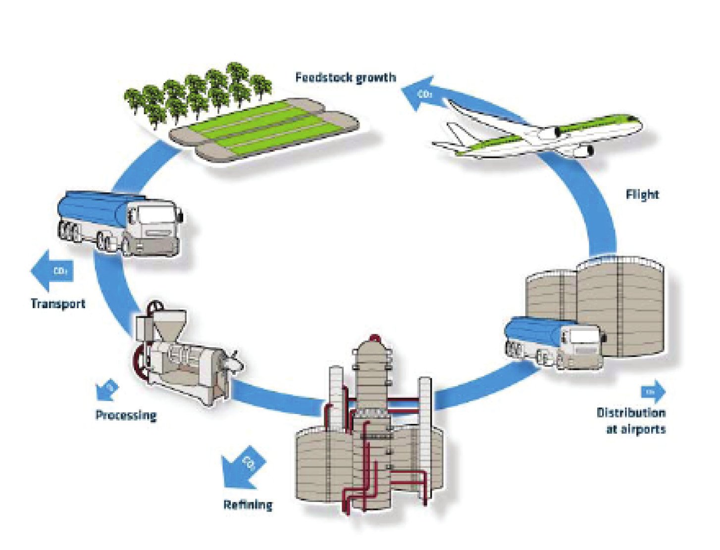
Production, transport and use of bio fuels
In the field of aviation it is the second generation bio-fuels that are used today. The first test flight was made in 2008 on a Boeing 747. One of the four engines of this plane was fed by a 50/50 mixture of kerosene and a bio-fuel derived from the “oil” class. The mixture did not affect adversely the functioning of the engine – it even showed a reduction in con- sumption of between 1% and 2%. Many research projects, of which some are funded by the European Commission, aim to obtain the certification of these mixtures in 2010-2011 and the certification of bio-fuels used alone before 2015.
It is, however, revealing to note that these biofuels emit 75% less CO2 than kerosene (taking account, of course, of the CO2 absorbed by the plants during their growth). The cost of such fuels is currently of the order of 80 or 90 dollars/barrel, which is not much more than the price of a barrel of petrol.
