1. Noise


While we notice airliners at a cruise altitude of 11 km only as condensation trail in the sky, the noise produced by starting and approaching airplanes in the vicinity of airports is annoying, especially for the residents close to airports. Therefore, the reduction of aircraft noise is a big challenge for aeronautical research. Although a lot of technical advances improved the situation within the last decades, the growth of air transport and the increasing expansions of airports require continuous research activities to exploit all possibilities for further improvements.
To think of noise reduction, it is necessary to understand how sounds are produced, propagated through a medium and how to assess them. Noise is not only specific to air transport, but can also be observed in everyday life. For sure, traffic noise of cars and trains plays a major role, but also the noise level in music clubs, at pop concerts, of MP3-players and diverse machinery. Their impact on people’s health should be taken into account.
Noise around us
Any sound, not matter what the source, is caused by something vibrating. Without vibration, there can be no sound. These vibrations cause the air particles next to the source to vibrate, and those air particles, in turn, cause the particles next to them to vibrate, and so on and so on, creating a sound wave. Just like a wave in water, the farther out the sound wave moves, the weaker it gets, until it completely dissipates.
If the original vibration creates a strong enough wave, it eventually reaches your ears and registers as a sound. You hear a sound because air vibrates against your eardrums, causing them to vibrate also. These vibrations are analyzed by your brain and registered as music, traffic, birds singing, etc.
The perception of sounds in day-to-day life is of major importance for human well-being. Communication through speech, sounds from playing children, music, and natural sounds in parklands, parks and gardens are all examples of sounds essential for satisfaction in every day life.
Sources of noise
When unwanted sound created by human beings hits our ears and disturbs the environment, noise pollution is created. All transportation systems (cars, trains, motorcycles, planes, helicopters) create noise pollution. Besides transportation noise, noise can come from barking dogs, loud music, air-conditioners, factories, power tools and construction work.
1.1. What is sound and how it is generated?
Sounds are connected with vibrations. If vibratory objects, e.g. a tuning fork, the string of a guitar or the membrane of a drum, move rapidly back and forth, they produce a sound or a tone.
A simple demonstration is a rubber band spanned over a box – it is a kind of a simplified guitar. The larger the deflexion of the rubber band the louder is its sound. Changing the thickness or the tension of the band, the frequency of its oscillation and so the pitch of the sound is changed. Similar observations can be made by using a scale ruler and cantilevering it over a table. The vibrations of a tuning fork can be visualised as well, e.g. by holding the handle of the intoned fork in a glass filled with water and watching the water surface.
The faster the vibration the higher is the produced tone. The larger the deflexion of the object the louder is the generated sound. This mechanism is well observable at music instruments. Touching the instruments, one can feel their fast see-saw action. Stopping the vibration results in disappearance of the sound. Air can also be excited to vibrations, e.g. by blowing or turbulences. Examples for this are the flute as musical instrument and blowing over partially filled bottles. The airflow around an object like e.g. an aircraft can produce noise as well.
Acoustic sources are connected with mechanical vibrations. Their properties can be described by means of their amplitude (maximum deflection) and their frequency (number of oscillations per time unit).
A rope in fast rotation produces a buzzing sound. Because the sections of the rope have different speeds, the induced sound consists of different frequencies and no clear tone is emitted. If the rope rotates quite slowly, the flow stays laminar without the presence of vortices and no noise is emitted.
At high air speeds the flow around an object becomes turbulent and produces vortices. A simple example is the flow around a cylindrical body. Left – and right-turning vortices are formed in the wake of the cylinder. At stationary flow conditions the vortices separate alternately forming the so called von-Karman-vortex street. The temporal offset of the separation on side A and B (see figure 2) induce a vibration to the body, which lead to the production of sound in the surrounding air. With increasing air speed the separation frequency increases and the tone pitch becomes higher.

1.2 Sound pressure
Sound pressure or acoustic pressure is the local pressure deviation from the ambient (average, or equilibrium) atmospheric pressure caused by a sound wave. Sound pressure can be measured using a microphone in air and a hydrophone in water. The SI unit for sound pressure p is the pascal (symbol: Pa).
White noise is thenoise created when all audible frequencies of sounds are combined at the same time and and the same density. It is similar in nature to withe light, which occurs when alla the colors of the spectrum are brought together. Whithe noise incorporates over 20.000 frequencies. The actual sound produced by white noise is compatible to rainsfall or ocean waves. It is gentle tone tnar can be found in nature. White noise combines all frequencies of sound ranging from very low tones to hight pitches
Sound pressure level (SPL) or sound level is a logarithmic measure of the effective sound pressure of a sound relative to a reference value. It is measured in decibels (dB) above a standard reference level.
Environmental noise is therefore measured with reference to a decibel scale, dB.
When noise is at 45 decibels, no human being can sleep, and at 120 decibels the ear is in pain and hearing begins to be damaged at 85 decibels.
Bandwidth is the difference between the upper and the lower frequencies in a continuous set of frequencies. This typically measured in hertz, and may sometimes refer to passband bandwidth, depending on context.
The human ear is more sensitive to sound in the frequency range 1 kHz to 4 kHz than to sound at very low or high frequencies. To compensate, sound meters are normally fitted with filters adapting the measured sound response to the human sense of sound. Common filters are: dB(A), dB(B) , dB(C) dB(A): The decibel A filter is widely used.
Using the dBA-filter, the sound level meter is less sensitive to very high and very low frequencies. Measurements made with this scale are expressed as dB (A).
dB(B) and dB(C): The decibel C filter is practically linear over several octaves and is suitable for subjective measurements at very high sound pressure levels. The decibel B filter is between C and A. The B and C filters are seldom used.
Any signal that can be represented as amplitude that varies with time has a corresponding frequency spectrum. This includes familiar concepts such as visible light (color), musical notes, radio/TV channels.
A source of light can have many colors mixed together and in different amounts (intensities). A rainbow, or prism, sends the different frequencies in different directions, making them individually visible at different angles. A graph of the intensity plotted against the frequency (showing the amount of each color) is the frequency spectrum of the light.
When all the visible frequencies are present in equal amounts, the perceived color of the light is white, and the spectrum is a flat line. Therefore, flat-line spectrums in general are often referred to as white, whether they represent light or sound or something else. Similarly, a source of sound can have many different frequencies mixed together.
The frequencies spectrum of a time-domain signal is a representation of that signal in the frequency domain. the frequency spectrum can be generated via a Fournier transform of the signal, and the resulting values are usualy presented as amplitude and phase, both plotted versus frequency.
Sound in our environment that we refer to as noise often comprise many different frequencies. When the frequency spectrum of a sound signal is flat, it is called white noise.
loudnes is that attribute of auditory sensation in terms of which sounds can be ordrered on a scale extending from quiet to loud.
Loudness is another characteristic of sound; it is a subjective measure. Filters such as A-weighting attempt to adjust sound measurements to correspond to loudness as perceived by the typical human. But, loudness perception is a much more complex process than A-weighting. As the perception of loudness varies from person to person it cannot be universally measured using any single metric.
1.3 Visualization of Vibrations
Vibrations can be visualised in vibration plots, in which the deflexion (amplitude) is plotted versus the time. The vibration plots of acoustic sources enable a closer analysis of the properties of the emitted sound. The amplitude is a measure for the sound level or loudness of sound. The frequency defined as the number of oscillations per time unit, describes the tone pitch. The higher the frequency the faster is the vibration and the higher is the tone.
1.4 How are sounds transmitted and how do sounds propagate?

Due to the vibration of an acoustic source the air molecules in its vicinity are excited to vibrations too. The air molecules vibrate locally which creates zones of compressions and rarefaction of the air particles resulting in local pressure fluctuations. By collisions with neighbouring particles these perturbations travel through the air as a sound wave. The sound wave doesn’t transport matter like an air flow but energy by air molecules exciting each other. While water waves oscillate transversally to their propagation direction, sound waves in the air propagate in longitudinal waves. The motion of the particles is in a direction parallel to the direction of the energy transport. It can be visualised by a magnet roll model or a slinky. In a free field a sound wave propagates homogeneously in all directions.

Soundgun
The vibrations propagate through the air and can excite other objects. The small air movements can not be observed with the human eyes directly, but their influence on other objects can be demonstrated by simple methods, e.g. a soundgun. This effect is used for hearing. The sound is bundled in the ear canal and excites the ear-drum. The induced vibrations were amplified in the inner ear and translated in electric signals which can be analysed further by the brain.
Vibrations generated by a sound source travel through the air and can excite vibrations of other objects. The vibrations propagate in all directions. Sound can also travel through liquids and solids but not through vacuum...
In contrast to electromagnetic waves, sound waves depend on a transmitting medium. Sound can travel through gases, liquids and solids, but not through vacuum. There are no sounds in outer space although some science fiction movies may imply it. A bell ringing in a vacuum tank can not be heard.
Sounds travelling through solids seem to be louder then sounds transmitted through air, because in most cases the sound is transmitted through smaller cross-sections compared to an omni-directional transmission in air. Due to this bundling of the sound waves in the solids more energy is transported to the receiver.
Speed of sound
The sound needs a certain time to travel through a media. The speed of the sound waves depends on the media they pass through. The speed of sound in air at 20°C amounts to 343 m/s. With this information the distance of a thunder storm can be determined. The light of a flash reaches the eyes immediately. Counting the seconds between the lightning and its thunder and dividing it by three gives a rough estimate of the distance to the thunderstorm in kilometres.

Longitudinal wave created in a slinky
The propagation of sound in air over long distances depends on different factors. If the noise of a remote motorway is still annoying or the words of a distant caller can be understood depends on different mechanisms. It can be influenced by constructional situations as well as for example by the weather. Like light, sound waves can be diffracted and refracted.
Absorption of air
When travelling through the atmosphere the sound energy is partially absorbed by molecular friction and other molecule properties. The absorption factor depends on the air temperature, the air humidity and the frequency of the sound wave. Usually it is given in dB/100m. With increasing temperature as well as with increasing humidity the absorption of sound decreases. Higher frequencies are absorbed much stronger than lower frequencies. That is why lower tones can travel longer distances than higher tones.
Refraction
Because the sound speed depends on the temperature, the temperature layering of the air influences the sound propagation. It is quite similar to the refraction of light. If the temperature decreases with increasing altitude, the sound is refracted upwards and at a certain distance of the source an area of reduced audibility occurs. For sound sources at ground level the distance of those acoustic shadow zones is about 200m. Contrary, an air temperature increasing with the altitude (inversion) results in a downward refraction of the sound waves. This causes a good audibility over large distances. In an analogous manner the sound propagation opposite to the wind direction results in an acoustic shadow zone of reduced audibility, whereas propagation in the wind direction causes a large range of audibility. The reason is that in both cases the wind velocity increases with increasing height due to the friction in the atmospheric boundary layer. The fluctuations in the sound level due to the weather condition at distances of 500 to 1000m can amount up to 20 to 30 dB.
Diffraction
Diffraction is a mechanism enabling sound waves to enter shadow zones, e.g. in shadowed areas behind buildings or through a small slot of an open window. Large low-frequency waves are diffracted stronger than short high-frequency waves.
Reflection
If sound waves strike the ground or a wall, they are reflected. Depending on the acoustic properties of the ground more or less sound energy is absorbed by the ground or the waves are reflected with a phase shift. A fluffy, porous surface, e.g. fresh snowfall absorbs more sound energy than hard and flat surfaces like a concrete wall. The highest ground absorption can be reached with the combination of a soft ground and a flat incidence angle, meaning the sound source and receiver are located close to the ground.
1.5 What makes sounds become noise and how to assess it ?
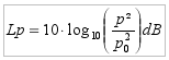
We define noise as an unwanted sound, annoying to people. Noise influences the human efficiency negatively and can cause damage to one’s health. Noise is not an exactly measurable physical quantity, but is perceived distinctly by every person. However, to measure the noise physically, Graham Bell (1847-1922) invented the logarithmic sound pressure level (SPL) or sound level Lp, inspired by the human ear. It is a measure of the effective sound pressure p of a sound relative to a reference value p0 =2*10-5 Pa, which is the threshold of human hearing (the quietest sound we can hear). It is measured in decibels (dB) above a standard reference level and defined by:
The sound pressure changes with the distance to the sound source. In a free field it is inversely proportional to the distance of a point-shaped sound source. In conclusion the measured sound pressure level also depends on the location of the measurement. The sound pressure describing the pressure fluctuations is small compared to the air pressure of 101.325 kPa at sea level. An overview of sound pressures and sound pressure levels are given in the table.
| Situation | Distance to sound source measurement location |
Sound pressure p (Pa) |
Sound pressure p Level Lp (dB) |
| Jet plane | 30m | 630 | 150 |
| Gunshot | 1m | 200 | 140 |
| Threshold of Pain | At the ear | 100 | 134 |
| Damage of hearing at short term exposure | At the ear | >20 | 120 |
| Fighter jet | 100m | 6.3 - 200 | 110-140 |
| Compresse air hammer/ music club | 1m/At the ear | 2 | 100 |
| Damage of hearing at long term exposure | At the ear | >0.36 | 85 |
| Main Road | 10m | 0.2 - 0.63 | 80 -90 |
| Car | 10m | 0.02 - 0.2 | 60 -80 |
| Television at room volume | 1m | 0.02 | ca. 60 |
| Spaeking person (normal chat) | 1m | 2 - 102 - 2 - 102 | 40-60 |
| Very quiet Room | At the ear | 2 - 104 - 6.3 - 104 | 20-30 |
| Rustling of leaves quiet breathing | At the ear | 6.32-5 | 10 |
| Threshold of human hearing at 2kHz | At the ear | 2 - 10-5(20 uPa) | 10 |
The logarithmic scale causes unusual relations when calculating sound levels. Thus using two similar in phase oscillating sound sources instead of only one, the sound level increases by 3dB. At free sound propagation a doubling of the distance to the sound source causes a reduction of the sound level by 6 dB, e.g. 68 dB in 100 m distance, 74 dB in 50 m distance and 80 dB in 25 m distance to the sound source. The sensitivity of the human ears to high and low tones is lower. If the frequency dependency of the human hearing is taken into account using the so called A-weighting curve the sound level in dB(A) is obtained. Our ears can detect sounds from 0 dB(A), the threshold of human hearing. At 120 dB(A) the threshold of pain for human hearing is reached.
1.6 How to detect noise sources ?
Humans are able to detect the direction from which a sound is coming. This is possible because of a time lag of a sound wave reaching locations a different distances to the sound source. This principle is also used by microphone arrays, also called acoustical cameras, to detect sound sources. A microphone array consists of multiple microphones in well known positions. Knowing the speed of sound and the position of the microphones, for every sound source position the time lag between the sound generation at the source and its arrival at the particular microphones can be determined. The signals of the microphones are shifted by the determined time lag for a particular sound source position, so they coincident on the time axis. Then the signals of all microphones can be added up resulting in a gain of the signal generated by the chosen sound source position, whereas signals generated by other sources are repressed. In further evaluation the frequencies and amplitudes of the signals are analysed. Doing this analysis for a complete observation area, a kind of a sound map can be obtained, visualising the sound source locations and sound level. That is why microphone arrays are also called acoustic camera.
1.7 Noise reduction
The principles of noise generation, sound propagation and wave properties of sound result in different strategies of noise reduction. The optimal approach is noise reduction at the sound source itself. It is easy to make a radio quieter or just switch it off. A minimisation of traffic noise at the sound source, e.g. cars, trains and aircrafts, is much more complicated.

Thus research about noise optimized design of vehicles is an important challenge. But the re-design of cars, trains and especially aircrafts deliver rather long-term improvements, because the development of new vehicle takes a certain time. A quite simple short-term method to reduce traffic noise is speed limitation. Therefore close to towns speed limits are enforced to control the noise of the road traffic. Also for aircrafts a speed reduction will lead to a noise reduction, but one has to take into account, that the aircraft must not go below the minimum air speed to keep it flying.

Aerodynamic sound sources on a half model in a wind tunnel at 70 m/s.
The increase of the distance to a sound source is a simple noise reduction method based on sound propagation, because the sound level decreases with increasing distance. The absorption of sound by the air contributes to a noise reduction as well. However, it is not always possible to reduce noise by increasing the distance. Another option for noise reduction is the use of sound insulating walls made of sound absorbing material.
Active noise control or anti-noise uses the interference of two or more sound waves to attenuate the sound. A noise-cancellation speaker emits a sound wave with the same amplitude but with inverted phase (also known as anti-phase) to the original sound, so effectively both waves cancel each other out. Noise-cancelling headsets are an example of active noise control. A microphone at the headphones measures the environmental noise and an inverted signal is generated in the headset to cancel the unwanted sound at the eardrum. Additionally, the headphones can play useful sounds like language. These kinds of headsets are used for helicopter pilots to attenuate the noise of the helicopter blades and enable a communication with the ground control and other passengers. For large areas noise cancellation is more difficult as the three dimensional wave fronts of the unwanted sound and the cancellation signal could match and create alternating zones of constructive and destructive interference. In small enclosed spaces (e.g. the passenger compartment of a car) a global cancellation can be achieved via multiple speakers and feedback microphones.
Ear protections, like earplugs or sound isolation headphones, are the final possibilities to protect the hearing from damage due to too much noise, if no other method is working. The use of such protection means is mandatory in the environment of loud machinery.
1.8 What causes the airplane noise?
Aircraft noise is noise pollution produced by any aircraft or its components, during various phases of a flight: on the ground while parked such as auxiliary power units, while taxiing, on run-up from propeller and jet exhaust, during take off, underneath and lateral to departure and arrival paths, over-flying while en route, or during landing.
The noise originates from three main sources:
- Aerodynamic noise
- Engine and other mechanical noise
- Noise from aircraft systems
- Aerodynamic noise
Aerodynamic noise arises from the airflow around the aircraft fuselage and control surfaces. This type of noise increases with aircraft speed and also at low altitudes due to the density of the air. Jet-powered aircraft create intense noise from aerodynamics. Low-flying, high-speed military aircraft produce especially loud aerodynamic noise.
The shape of the nose, windshield or canopy of an aircraft affects the sound produced. Much of the noise of a propeller aircraft is of aerodynamic origin due to the flow of air around the blades. The helicopter main and tail rotors also give rise to aerodynamic noise. This type of aerodynamic noise is mostly low frequency determined by the rotor speed.
Typically noise is generated when flow passes an object on the aircraft, for example the wings or landing gear. There are broadly two main types of airframe noise:
- Bluff Body Noise (circular cylinder - fuselage) - the alternating vortex shedding from either side of a bluff body, creates low pressure regions (at the core of the shed vortices) which manifest themselves as pressure waves (or sound). The separated flow around the bluff body is quite unstable, and the flow "rolls up" into ring vortices - which later break down into turbulence.
- Edge Noise - when turbulent flow passes the end of an object, or gaps in a structure (high lift device clearance gaps) the associated fluctuations in pressure are heard as the sound propagates from the edge of the object. Engine and other mechanical noise
Much of the noise in propeller aircraft comes equally from the propellers and aerodynamics. Helicopter noise is aerodynamically induced noise from the main and tail rotors and mechanically induced noise from the main gearbox and various transmission chains. The mechanical sources produce narrow band high intensity peaks relating to the rotational speed and movement of the moving parts. Aircraft Gas Turbine engines (Jet Engines) are responsible for much of the aircraft noise during takeoff and climb. With advances in noise reduction technologies - the airframe is typically noisier during landing.
The majority of engine noise is due to Jet Noise - although high bypass-ratio turbofans do have considerable Fan Noise. The high velocity jet leaving the back of the engine has shear layer instability (if not thick enough) and rolls up into ring vortices. This of course later breaks down into turbulence.
Noise from aircraft systems
Cockpit and cabin pressurization and conditioning systems are often a major contributor to noise within cabins of both civilian and military aircraft. One of the most significant sources of cabin noise from commercial jet aircraft other than the engines is the Auxiliary Power Unit (or APU). An Auxiliary Power Unit is an on-board generator used in aircraft to start the main engines, usually with compressed air, and to provide electrical power while the aircraft is on the ground. Other internal aircraft systems can also contribute, such as specialized electronic equipment in some military aircraft.
Particular attention must be paid to structural design and material selection so that vibrations are transmitted less effectively. For reducing the cabin noise, aircraft cabins now incorporate more advanced materials included in sound-absorbent seats, cabin walls, acoustic isolation and electronic noise cancellation systems.
For anyone living next to an airport, constant noise from aircraft can pose serious long-term health problems caused by stress, lack of concentration and loss of sleep. The number of flights is expanding very fast, and we need to be looking for new technologies that reduce noise more efficiently. Airplanes typically land in "staircase-like" paths, reducing their altitude in a series of steps towards an airport. Each step requires a noisy engine thrust to level out the aircraft after moving to a lower level. Mostof the noise is generated at the lowest step. Some airports are already using an alternative "continuous descent approach," in which the aircraft maintains a cruise altitude until it is relatively close to an airport, at which point it makes an even, continuous descent to the runway. This can more than halve the noise level. It can also reduce fuel emissions and slightly shorten flight time, since the plane operates at lower power settings, maintains higher altitudes and speeds, and takes more direct paths to the runway.
Noise reduction in air transport
To reduce the noise impact in the vicinity of airports aeronautical research also aims for noise reduction at the sound source. Great successes were already achieved in the past, comparing the sound level of old and modern airplanes. Nevertheless experts estimate that the noise level of the engine can be further reduced by nearly 10 dB. So, modern concepts for noise reduction of aircrafts must be investigated, especially taking into account the long design process of new aircraft types. For modern aircrafts the noise generated by the jet of the engines could already be improved a lot compared to older models. Nowadays the fan located in the intake of the aircraft engines comes to the focus of the acoustic research. One possibility investigated is the usage of active noise control to attenuate the quite annoying tonal components of the fan noise. The feasibility of the classical approach of a loudspeaker-microphone combination was already demonstrated by researchers. A new approach is the usage of aerodynamic anti-noise sources, like well-directed air injection by pressurized air, which is more practicable for this application.
Aircraft noise is dominated by the noise of the engines, so the airframe noise due to air flow is only relevant for the approach at low thrust of the engines. The base for the reduction of the airframe noise is a detailed analysis of the mechanisms of aerodynamic sound generation. Wind tunnel tests showed for example that a main component of the airframe noise is generated by the slat of the high lift system of the wing. Such wind tunnel tests use microphone arrays to detect and visualize sound sources which enable the investigation of the effectiveness of several approaches of noise reduction. The measured acoustic data are also used to validate numerical methods to predict aerodynamic sound sources. Those prediction tools can be used in an early stage of the design process to optimize an aircraft acoustically. A further approach is the investigation of noise-optimised take-off and landing procedures. It is mainly based on an optimisation of the flight altitude, the engine performance, speed and the aerodynamic configuration of the aircraft. At the enlarged airport area a reduction of the noise level by nearly 3 dB is possible. There are mainly two possibilities to reduce the aircraft noise. Firstly, there is the reduction of the thrust of the engine, because the engines have a large sound emission. Secondly, the distance between aircraft and ground can be enlarged, because the atmosphere attenuates the noise. To optimize the take-off and landing procedures a lot of criteria must be taken into account. Beside the noise reduction also economic and safety aspects must be considered. New procedures must not lead to additional stress for the pilots. To avoid a loss of the airport capacity they must not be more time consuming. For economical and environmental reasons a reduction of fuel consumption is desired. Finally noise reduction is an inter-disciplinary challenge, for which the overall system of an aircraft and many different requirements must all be considered to find the best compromise.